DIY RFID Smart Lock with Arduino

The MFRC522 reader can read and write data to RC522 chips, and stores this data in the Arduino’s EEPROM. This would be a great addition to any DIY setup, and is especially relevant to any basic home security system. It could be used alongside DIY alarm systems or DIY security camera systems.

You Will Need ( you can get from Incotel)

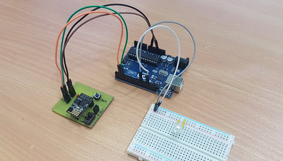
  • Arduino. We’ve used an Uno, though any Arduino board or clone will suffice.
  • 3 x 220 ohm resistors
  • 1 x 10k ohm resistor
  • Logic-level N channel Mosfet
  • MFRC522 module with at least two cards/fobs to read. Most come with one of each, and can be bought for  cheap price, but you probably already have one in your wallet in the form of a public travel card.
  • Red, blue, and green LEDs
  • 12v Solenoid ($5)
  • 12v power supply
  • Breadboard and hook up wires

The MFRC522 Module

The star of this setup is a cheap MFRC522 module, which came with both a card and fob containing an s50 chip, each storing its own unique permanent identification number (UID). These are both functionally identical, just in a different shape.

module and card

Begin by searching for the MFRC522 library in the library manager of your Arduino IDE, and install it. Alternatively you can download the library and install it manually to the libraries folder. If you are totally new to Arduino you might find this primer for getting started useful!

Getting Started With Arduino: A Beginner’s Guide Getting Started With Arduino: A Beginner’s Guide Arduino is an open-source electronics prototyping platform based on flexible, easy-to use hardware and software. It’s intended for artists, designers, hobbyists, and anyone interested in creating interactive objects or environments.

The library also contains a Fritzing diagram, which I have annotated indicating how to attach the module to your Arduino.

arduino rfid pinout wiring
Image Credit: Miguel Balboa via Github

Be careful: this board works on 3.3V, not 5V, so take care to connect it to the right pin.

To test the setup, open the DumpInfo sketch from File > Examples > MFRC522 > DumpInfo and upload it to your Arduino board. Open the serial monitor, and hold one of your RFID objects up to the reader. You should see something like this:

dump info serial readout

If you get errors in the read out saying MIFARE_Read() failed: Timeout in communication, or PCD_Authenticate() failed: Timeout in communication, don’t worry. It likely means you did not hold the tag up to the reader for long enough to read all of the data. As long as you get the card UID (which is read as soon as the tag is within range of the reader), it will work with this project. If you are not getting a reading at all, check your wiring and try again.

The Rest of the Circuit

Now that we have verified that our module works, lets add the rest of the components. Connect your components like this:

full setup circuit fritzing

  • Our 12v power supply (unplugged for now) connects to the rails of our breadboard. Connect the Arduino GND pin, and MFRC522 GND pin to the ground rail.
  • The LEDS are connected to pins 2, 3, and 4 and to the ground rail through 220 ohm resistors.
  • Our MOSFET’s gate leg (left on image) connects to pin 5, and to ground through a 10k ohm resistor. The drain leg (middle) connects to the negative terminal of our 12v solenoid, and the source leg (right) connects to the ground rail.
  • Connect the positive terminal of the 12v Solenoid, and the VIN of the Arduino to the 12v rail on the breadboard.

With this setup, whenever we send a HIGH signal from the Arduino to the MOSFET, it will allow the current to pass to the Solenoid. There is nothing to stop you from using a higher powered or more heavy duty solenoid, though you’d need a stepdown transformer to power the Arduino from higher than 12V. Also pay close attention to the datasheet for your MOSFET to make sure you wouldn’t be overloading it.

Once it’s all put together it should look something like this:

circuit layout

While it isn’t necessary, I created a little rig to simulate a door lock from scrap wood.

Modifying the Sketch

With the circuit built, it’s time to set up our Arduino Sketch. Conveniently, the MFRC522 library comes with an example sketch called Access Control that does almost exactly what we want to do. Connect your Arduino to your computer, and open File > Examples > MFRC522 > AccessControl in the Arduino IDE.

There is a wealth of information provided both in the example sketch, and on the GitHub page for the library. We only need to modify a few lines. Alternatively, you can download our modified code from this GitHub Gist.

Firstly, the sketch was designed for a circuit with a single RGB LED using a common anode. We won’t be using that, so simply comment out this section.

//#define COMMON_ANODE

Now, match our LED pins to those defined in the sketch.

#define redLed 3    // Set Led Pins
#define greenLed 4
#define blueLed 2

We need to change the relay pin (although we are using a MOSFET in this case) to match our setup.

#define relay 5  // Set MOSFET Pin

To make it easier to change how long the lock stays open later, we will create a variable for it.

int lockDelay=10000; // lock stays open for 10 seconds.

We only need to make one more change. Right at the bottom of the loop method, buried in an if statement is the method call granted(300). We need to change this so that it uses our lockDelay variable.

granted(lockDelay); // Open the door lock for lockDelay duration

Save the sketch under a new name, and upload it to your Arduino. When it’s finished, open the serial monitor. The first time you do this, it will ask for you to scan something to use as your master card. Hold your card up to the reader, and the UID of the card should display on the serial monitor, along with the message Everything Ready

That’s it! Your master key is all set up. Unplug your Arduino board from the computer. Your master key details will be saved in the Arduino’s EEPROM, even after the power is turned off.

Testing the Full Setup

Take one last quick look over your wiring to check everything is in place, and connect your 12v power supply. At this point, it is worth mentioning that you should be wary of the duty cycle of your solenoid. The cheap solenoid I am using for this test does not have a 100 percent duty cycle, consequently it should not be left in it’s locked position for long periods of time. To make this into a permanent setup, use a 100 percent duty cycle solenoid. Even better would be a normally closed (NC) solenoid, which remains locked when it is not powered. This also means that anyone wanting to bypass the system cannot simply unplug it!

When the circuit is powered up, the Blue LED should light up to show that the device is operational. Holding the master card over the reader puts it in admin mode should cause all three LEDs to flash. While they are flashing you can hold other cards or fobs over the reader to add or take away access rights. It will flash green for giving access, and blue for taking away. Use the master card again to exit admin mode.

Now when you hold a card or fob with access up to the reader it should flash green and open the lock. If it flashes red, access has been denied!

rfid arduino open lock

All Done!
article credit for : makeuseof.com


In this ESP8266 WiFi Module Project, we will learn about WiFi Controlled LED using ESP8266 and Arduino. I will show you how to control an LED connected to the Digital I/O Pin of the Arduino over WiFi Network using the ESP8266 WiFi Module.

Table of Contents

Overview

The ESP8266 WiFi Module is an interesting addition to the makers and hobbyists’ community as it allows us to integrate WiFi and Internet into our DIY Projects.


IoT or Internet of Things is one such area which can be implemented using a variety of sensors connected to a Microcontroller like Arduino and ESP8266 WiFi Module to access the sensor data from anywhere in the World.

Before thinking about big IoT projects, let us begin exploring the ESP8266 WiFi Module and implement a small but useful project called WiFi Controlled LED using ESP8266 and Arduino. 


we have already introduced to you about the ESP8266 WiFi Module in my GETTING STARTED WITH ESP8266 AND ARDUINO Project. Refer to that project first in order to learn about the basic information on ESP8266 WiFi Module, its Pin Diagram, pin configuration and how to interface ESP8266 with Arduino.

IMPORTANT NOTE:

  • In my second project on ESP8266 WiFi Module, I have shown you How to flash the AT Command Firmware onto the ROM of ESP8266 WiFi Module.
  • It is very important that you first implement that project i.e. make sure that your ESP8266 WiFi Module has AT firmware installed on it.
  • If you have programmed your ESP8266 WiFi Module with other program (like Blink, for example), then you must flash the firmware. If your ESP module is already has the AT Commands firmware, then leave it as it is.

Concept behind WiFi Controlled LED using ESP8266 and Arduino

Before getting into the details of the project like the circuit diagram, components, connections and the code, let me take you through the concept behind the WiFi Controlled LED using ESP8266 and Arduino.

The idea behind the project is very simple. Connect an LED to the Arduino Board. This LED must be connected over WiFi i.e. within a local network through a Smart Phone or a Laptop.

For this, use the ESP8266 WiFi Module and interface it to Arduino through Serial Communication. Arduino will command the ESP8266 module to get connected to a WiFi network and receive data from the client (an HTML page).

Based on the information sent by the client (with the help of a Web Browser), the Arduino will either turn ON or OFF the LED. That’s it.

Circuit Diagram

The circuit diagram for the WiFi Controlled LED using ESP8266 and Arduino project is shown I in the image below.


Components Required  
[Buy Here]

  • Arduino UNO  
  • ESP8266 WiFi Module 
  • LED  
  • 330Ω Resistor (1/4 Watt)   
  • 1 KΩ Resistor (1/4 Watt)   
  • 2.2 KΩ Resistor (1/4 Watt)  
  • Push Button   
  • Connecting Wires  
  • Mini Breadboard  

Circuit Design

I have used the software serial feature of the Arduino and made its digital pins 2 and 3 as RX and TX. These pins must be connected to TX and RX Pins of the ESP8266 WiFi Module.

NOTE: I have used a level convertor consisting of a 1 KΩ Resistor and a 2.2 KΩ Resistor before connecting the TX Pin of Arduino (Pin 3) to the RX Pin of the ESP8266.

An LED is connected to the Digital I/O Pin 11 of the Arduino. (This is the LED that we will be controlling over WiFi).

Coming to the rest of the connections with respect to the ESP8266, it’s VCC and CH_PD pins are connected to 3.3V of the Arduino and GND is connected to, well the GND pin of the Arduino. A Push Button is connected between RESET of ESP8266 and GND.

Both the GPIO Pins of the ESP8266 i.e. GPIO0 and GPIO2 are left open as we won’t be using those pins in this project.

Code

The following is the code that is to be uploaded into Arduino. It will configure the WiFi in the ESP8266 Module as well as check for the data from the HTML  page

#include <SoftwareSerial.h>
SoftwareSerial esp8266(2,3); //Pin 2 & 3 of Arduino as RX and TX. Connect TX and RX of ESP8266 respectively.
#define DEBUG true
#define led_pin 11 //LED is connected to Pin 11 of Arduino


void setup()
  {
    pinMode(led_pin, OUTPUT);
    digitalWrite(led_pin, LOW);
    Serial.begin(9600);
    esp8266.begin(115200); //Baud rate for communicating with ESP8266. Your's might be different.
    esp8266Serial("AT+RST\r\n", 5000, DEBUG); // Reset the ESP8266
    esp8266Serial("AT+CWMODE=1\r\n", 5000, DEBUG); //Set station mode Operation
    esp8266Serial("AT+CWJAP=\"SSID\",\"Password\"\r\n", 5000, DEBUG);//Enter your WiFi network's SSID and Password.
                                   
    while(!esp8266.find("OK")) 
    {
      }
    esp8266Serial("AT+CIFSR\r\n", 5000, DEBUG);//You will get the IP Address of the ESP8266 from this command. 
    esp8266Serial("AT+CIPMUX=1\r\n", 5000, DEBUG);
    esp8266Serial("AT+CIPSERVER=1,80\r\n", 5000, DEBUG);
  }

void loop()
  {
    if (esp8266.available())
      {
        if (esp8266.find("+IPD,"))
          {
            String msg;
            esp8266.find("?");
            msg = esp8266.readStringUntil(' ');
            String command1 = msg.substring(0, 3);
            String command2 = msg.substring(4);
                        
            if (DEBUG) 
              {
                Serial.println(command1);//Must print "led"
                Serial.println(command2);//Must print "ON" or "OFF"
              }
            delay(100);

              if (command2 == "ON") 
                    {
                      digitalWrite(led_pin, HIGH);
                    }
                   else 
                     {
                       digitalWrite(led_pin, LOW);
                     }
          }
      }
  }
   
String esp8266Serial(String command, const int timeout, boolean debug)
  {
    String response = "";
    esp8266.print(command);
    long int time = millis();
    while ( (time + timeout) > millis())
      {
        while (esp8266.available())
          {
            char c = esp8266.read();
            response += c;
          }
      }
    if (debug)
      {
        Serial.print(response);
      }
    return response;
  }
 

HTML Code for Sending Data to ESP8266

In order to create an interface for the project, I have created a simple HTML based webpage. The HTML code for this webpage is given below.

<!DOCTYPE html >
<html>
<head>
<title>WiFi controlled LED</title>
<script src="jquery.js"></script>

</head>
<body>
<h2> <i> WiFi Controlled LED using Arduino and ESP8266 </i> </h2>
<h4> <i> Enter the IP address of ESP8266 </i> </h4>
<div style="margin: 0; width:400px; height:30px;">
<FORM NAME="form" ACTION="" METHOD="GET">
ESP8266 IP Address:
<INPUT TYPE="text" NAME="inputbox" VALUE="" />
</FORM>
</div>
<h3> Click to toggle LED! </h3>
<input type="button" NAME="butname" value="Turn ON LED" />
<p>STATUS: LED is OFF!</p>
</body>
<script>
$.ajaxSetup({timeout:1000});
btn = document.querySelector('input[name="butname"]');
txt = document.querySelector('p');
btn.addEventListener('click', led1);

function led1()
{
	var val1 = 'OFF';
	if (btn.value === 'Turn OFF LED') 
	{
	btn.value = 'Turn ON LED';
	val1 = 'OFF';
	txt.textContent = 'STATUS: LED is OFF!';
	} 
	else 
	{
    	btn.value = 'Turn OFF LED';
	val1 = 'ON';
    	txt.textContent = 'STATUS: LED is ON!';
	}
	TextVar = form.inputbox.value;
	ArduinoVar = "http://" + TextVar + ":80/";
	$.get( ArduinoVar, {led: val1})	;
	{Connection: close};
}
</script>
</html>


Download this HTML Code (save it as .html file).

This HTML webpage uses the JavaScript library “jQuery.js”. Download this library from hereand place it in the same folder as the .html file.

So, your webpage folder consists of two file: one “webpage.html” file and a “jQuery.js” file. Open the HTML file using any web browser. The interface looks like this.

Working of WiFi Controlled LED using ESP8266 and Arduino Project

Upload the Arduino Code provided above to your Arduino Board after making all the necessary connections. Once the code is uploaded, open the Serial Monitor of Arduino. You can see the progress of the setup done on the ESP8266 WiFi Module.


Some of the information in the above image looks garbage but I assure that correct data is transmitted. If you got a clean response, you can find the IP Address of the ESP8266 Module at the highlighted place in the image above.

Since I couldn’t find the IP Address from Serial Monitor, I had to look up for it using another tool called “Advanced IP Scanner”.

Now, open the webpage that you saved earlier and enter this IP Address in the IP Address field provided. After entering the IP Address, you can click on the Button on the page to turn ON and OFF the LED.

Conclusion

A simple project called WiFi Controlled LED using ESP8266 and Arduino is designed here where an LED connected to Arduino is controlled over WiFi (within the same network).

Any device connected in same WiFi Network can control the LED with the help of a simple HTML webpage.

The next step or an advanced version of this project will be controlling the LED over internet i.e. from anywhere in the World (involves PORT Forwarding).

Project by : electronicshub.org